What are the types of electrical tests?
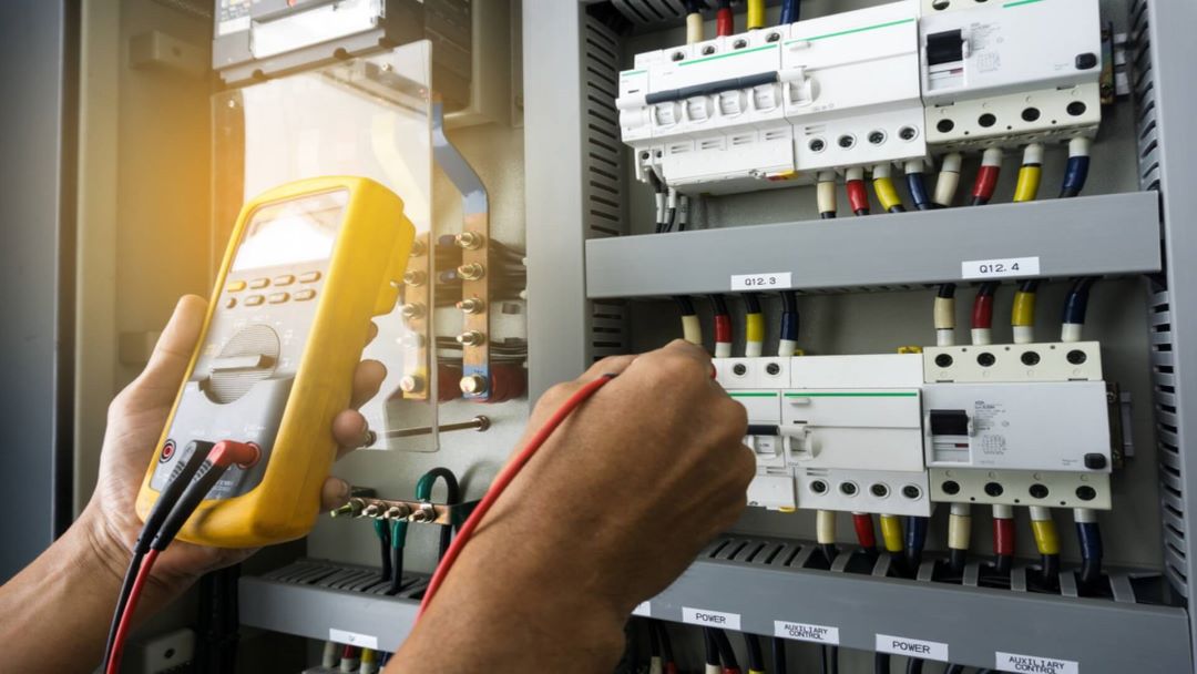
The types of electrical tests cover a broad spectrum designed to ensure safety, functionality, and reliability in various electrical components and systems. Electrical testing includes but is not limited to insulation resistance test, continuity test, earth grounding test, and high-potential (hi-pot) test.
Each electrical test serves a specific purpose, from verifying the integrity of electrical insulation to ensuring the safety of electrical installations. These tests are essential in identifying potential problems before they lead to equipment failure or safety hazards, making electrical testing a critical component of maintenance routines and safety protocols.
What are the 5 electrical tests?
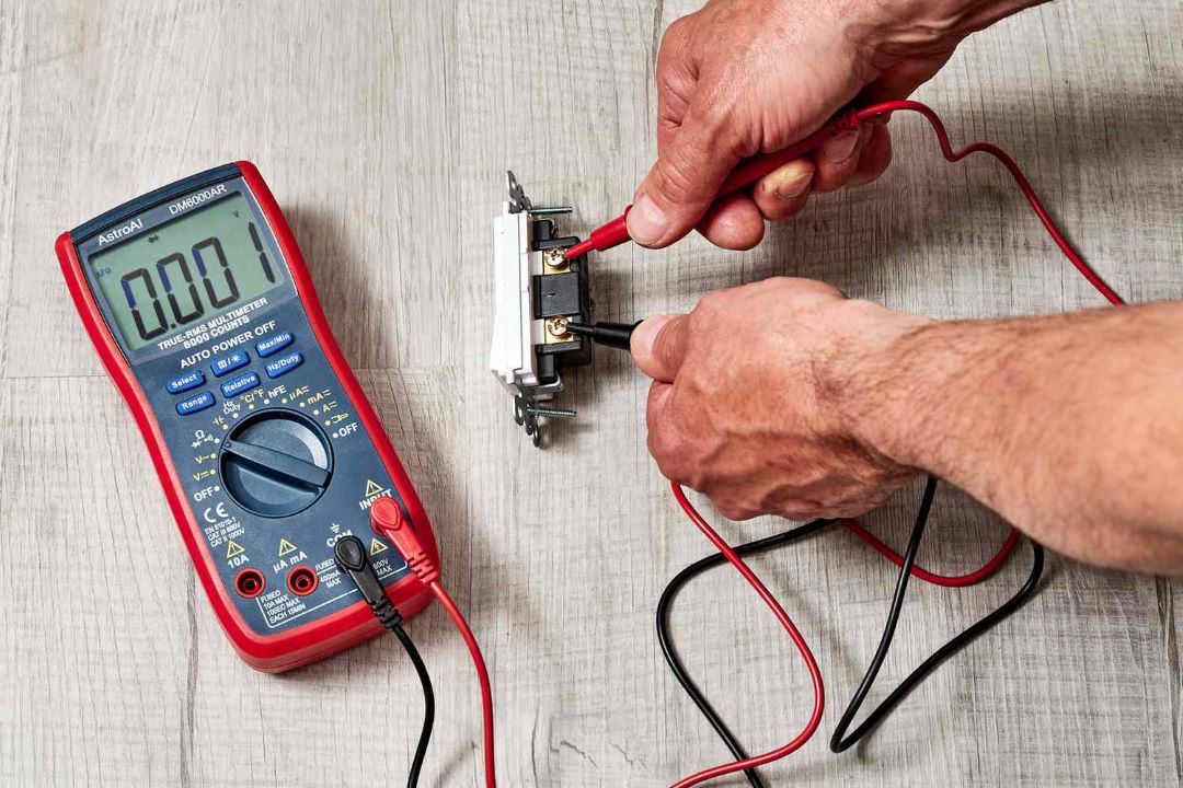
The 5 electrical tests are namely Insulation Resistance Test, Earth Continuity Test, Polarity Test, Earth Leakage Test, and Loop Impedance Test.
Each of these electrical tests plays a critical role in ensuring the safety, functionality, and efficiency of electrical systems.
The insulation resistance test (IR test) is essential for testing the integrity of electrical insulation, thereby preventing leakage currents that could lead to shocks.
The earth continuity test verifies that electrical paths are securely grounded to avoid electrical hazards.
Polarity testing ensures that connections are made correctly in the circuit, critical for the functionality of electrical installations.
The earth leakage test is conducted to identify unwanted leakage currents to earth, which can be an indicator of potential electrical faults.
Lastly, the loop impedance test assesses the overall impedance of the earth loop, which is crucial to ensure that if a fault does occur, the protective devices in the electrical installation will operate correctly.
Collectively, these electrical tests act as preventive measures against electrical failures and safeguard against electrical risks, emphasizing the importance of thorough and regular electrical testing for electricity in both residential and commercial settings.

What is the correct way to conduct electrical tests in order?
In order, the correct way to conduct electrical tests is to first perform electrical dead testing, followed by live testing. This sequence ensures safety and the integrity of the electrical system being evaluated.
What is an electrical dead test? An electrical dead test involves testing an electrical circuit when it is not energized. The purpose is to check the continuity of circuits, the integrity of insulation, and to verify that there are no shorts or earth faults. Electrical dead testing is crucial as it allows for the identification of potential hazards without the risk of electric shock.
The electrical dead testing procedure typically includes tests such as continuity testing, insulation resistance testing, and polarity testing. These are conducted using specialized equipment designed to measure electrical properties without the need to energize the circuit.
Following dead testing, electrical live testing is conducted to ensure the circuit behaves as expected under normal operating conditions. This includes testing for voltage presence, phase rotation, and verifying the operation of protective devices and circuit breakers.
The testing sequence order prioritizes safety and accuracy, beginning with dead tests to ensure the system can safely be made live for subsequent tests. By adhering to this sequence, technicians can safely conduct electrical testing, minimizing the risk to themselves and ensuring the reliability and safety of electrical installations.
How to conduct the 5 methods of electrical wiring testing in sequence?
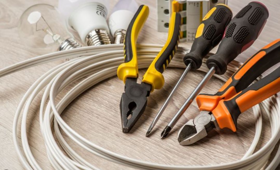
In sequence, the 5 methods of electrical wiring testing should be conducted to the steps listed below:
- Visual Inspection.
- Insulation Resistance Test (IR test).
- Earth Continuity Test.
- Polarity Test.
- Earth Fault Loop Impedance Test.
These electrical test methods are conducted to ensure optimum safety and compliance with regulatory standards.
Initially, a visual inspection is essential to identify any overt signs of damage or wear that may impede the integrity of the electrical installation.
Following this, insulation resistance testing is performed to check for any potential breakdown in the electrical insulation, which can prevent electric shocks.
The continuity of protective conductors including earth and bonding tests ensures a clear path is available for fault current to flow to earth, a critical component for the safety of electrical systems.
Subsequently, current leakage is measured by using reverse polarity method. A polarity test is conducted to assure that connections are correctly made and that the flow of electricity is in the proper direction.
Finally, the earth fault loop impedance test is carried out to ascertain the effectiveness of the earthing system, confirming that it is sufficient to activate the protective device in case of a fault.
Together, these electrical tests form a comprehensive electric testing protocol that underpins safety procedures.
What are the types of electrical testing equipment?
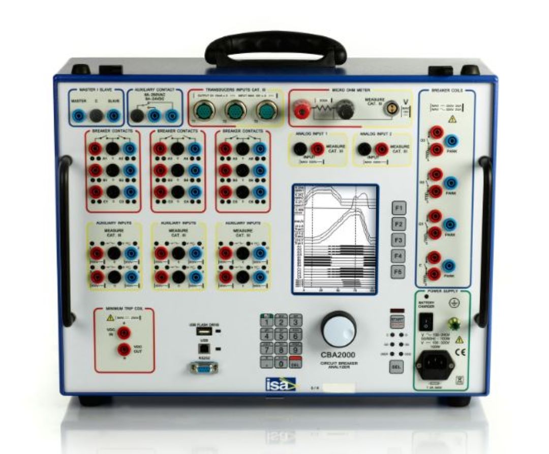
The types of electrical testing equipment list range from simple handheld devices such as multimeters to complex, automated testing systems designed for specific industry applications, in particular: oscilloscopes, circuit breaker analyzers, and power tequality analyzers.
Basic electrical test equipment includes multimeters, which measure voltage, current, and resistance; insulation testers that assess the integrity of electrical insulation; continuity testers for checking circuits; and earth/ground resistance testers to ensure safety and compliance with regulations.
Additionally, more specialized equipment such as oscilloscopes, circuit breaker analyzers, and power quality analyzers are employed for in-depth analysis of electrical systems.
Suppliers of electrical testing equipment offer a wide array of products, catering to the needs of both basic electrical troubleshooting and advanced diagnostic testing.
This ensures that professionals involved in electrical testing can select from the latest technologies to perform efficient and accurate tests, enhancing the overall safety and reliability of electrical installations and systems.

What are the 5 golden rules of electrical?
The 5 golden rules of electrical are namely:
1) Turning Off All Mains and Electrical Equipment Before Electrical Testing.
This step ensures the safety of personnel by eliminating potential electrical hazards. Turning off all power sources is typically performed as a preliminary measure in line with industry standards to create a safe environment for subsequent testing.
2) Verify Voltage Absence Using Approved Voltage Testers.
To confirm the absence of live voltage, approved voltage testers such as Fluke are used. This test, typically performed following the disconnection of power, adheres to industry standards to prevent electrical shocks.
3) Maintain A Safe Distance Or Use Appropriate Insulating Barriers.
Keeping a safe distance or utilizing insulating barriers minimizes the risk of accidental contact with live electrical components. This precaution, guided by industry standards, is typically performed during electrical testing to ensure worker safety.
4) Ensure proper grounding of electrical systems before initiating any work.
Proper grounding of electrical systems is crucial to prevent accidents. This process, typically performed as a fundamental safety measure, complies with industry standards to ensure that any fault current has a safe path to the ground.
5) Always Wear Personal Protective Equipment (PPE).
Wearing PPE is essential for protecting individuals from electrical hazards. This safety practice, typically performed throughout the testing process, aligns with industry standards to minimize risk of injury.
What are the 5 electrical tests to be carried out before a circuit can be made live?
Before a circuit can be made live, the 5 electrical tests to be carried out are Insulation Resistance Testing, Continuity Testing, Polarity Testing, Earth Fault Loop Impedance Testing, and RCD (Residual Current Device) Testing.
Each electrical test serves a critical role in ensuring the safety and functionality of the electrical system. Thus, ensuring fire safety in electrical installations and emphasizing the importance of electrical inspection for any potential risks or faults that must be addressed.
What is the basic electrical testing?
The basic electrical testing is an evaluation of the parametric, functional, or timing performance of a component when electrical power is applied.
This testing ensures that the component operates within the specified parameters and meets the desired functionality.
By applying electrical signals and measuring the response, engineers can identify defects, verify compliance with design standards, and confirm the reliability of the component under operational conditions.